
Intelligent Control for the Smart Foundry
Nearing the quarter of the 21st century, it seems technology is advancing faster and faster every year. Why shouldn’t your facility advance too? This post will provide some options for you to consider as you’re researching, designing, and improving your process.
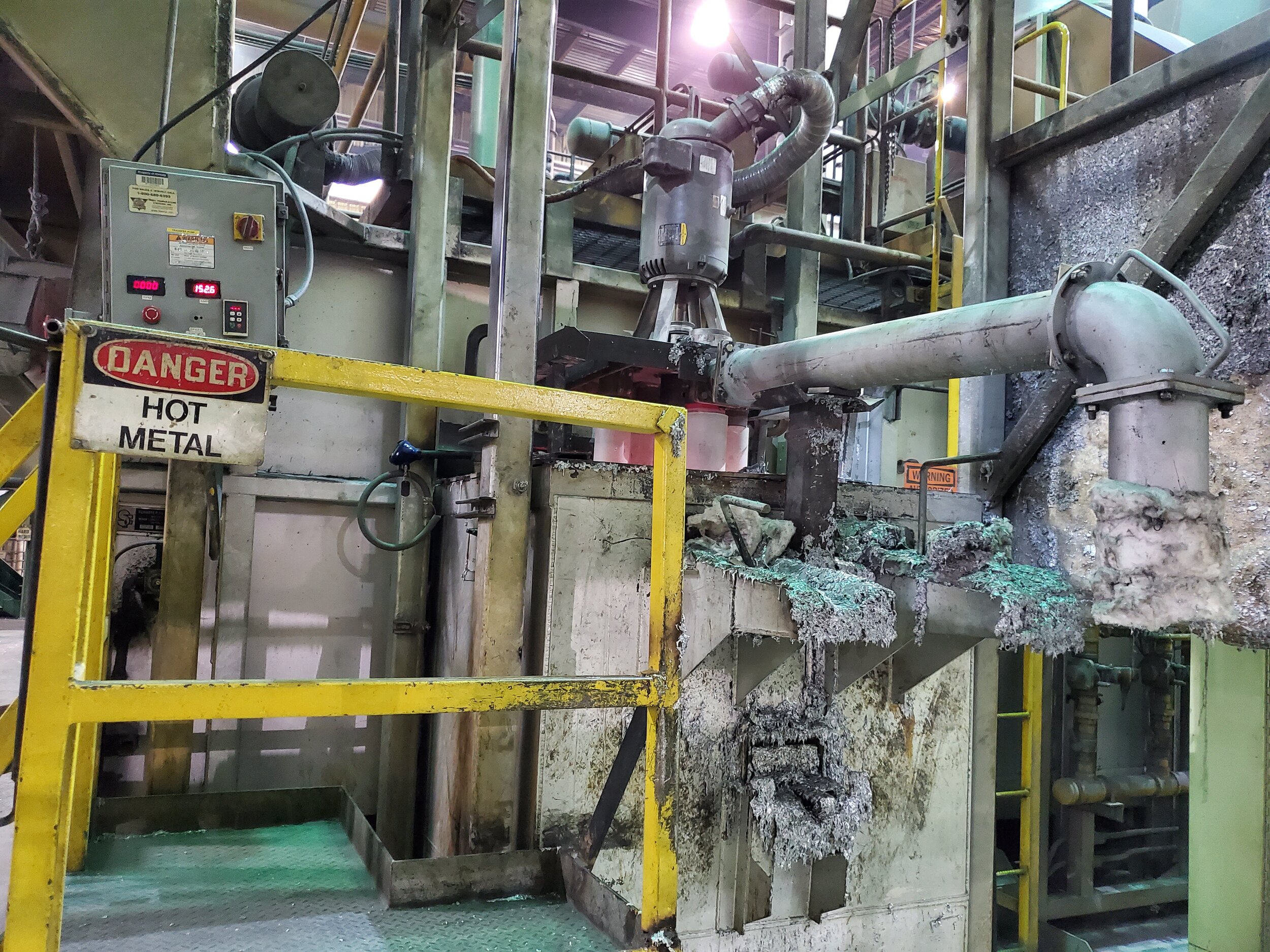
When we step into the foundry we accept the reality that we are always at the mercy of the laws of physics, namely thermal transfer and thermal expansion. When humans are added to the equation, rapid thermal transfer and expansion means severe injury or death. I am referring of course to the ever-present possibility of human contact with the liquid metal. Make no mistake (for it could be your last!), our line of work is not for the faint of heart. Human casting should be left to Han Solo in the movies, not to your local aluminum casthouse!
Safety is and must always be the absolute, 100%, number one top priority.
When looking for a solution, you have to have the confidence not only that it will perform as expected, but also that it will provide a safer work environment for all those involved. We’re asking our equipment to run in one of the most hazardous environments, but we must demand all of this and more if we are to keep up with the ever-changing industrial landscape of the 21st century.
The System
We have devoted countless hours to designing such a system, with great help from our research partners and loyal customers willing to take the next step in metal evolution. This control system can be used with our any of our pumps, including our transfer pumps, circulation pumps, dual stage Chameleon®, Coriolis® chip melting vortex and more!
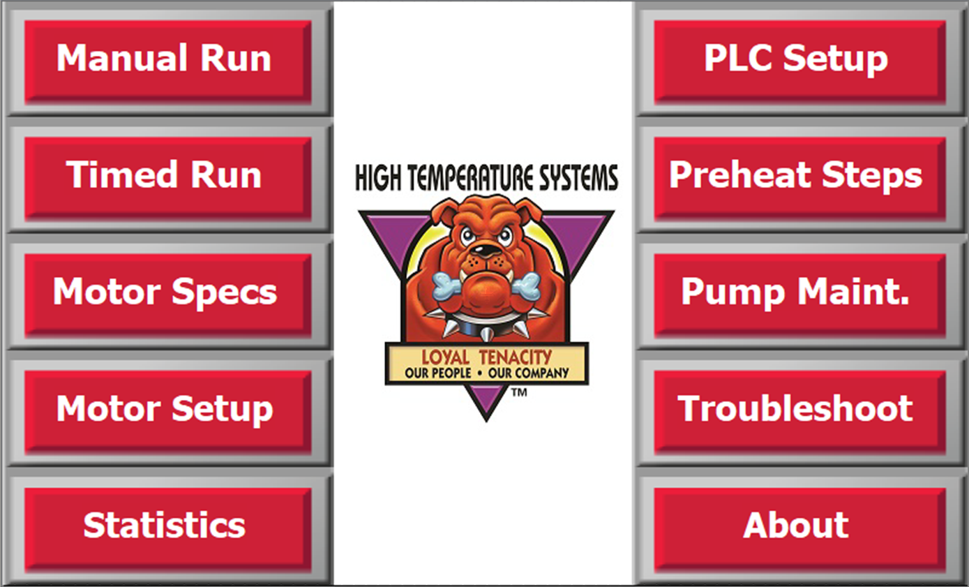
Control Panel Home Screen
The screen shown here is what you’ll see on our latest control panels. The internal wiring will vary dependent on the end-user’s pump size and function, facility capabilities, local voltage and frequency, certification requirements (such as CE, CSA, UL, etc.) A full detailed manual and quick-start guide is provided with every system.
Here’s what’s included:
Manual or Timed Operation
For ease of use - once the system has been initially configured - operators can start or stop the pump simply with the press of a button.
Need your transfer pump to run a sequence for exactly 7 seconds? Set your time and select “Timed Run” to run the pump for the specified time.
Motor Specs
This page lists the motor specifications as given on the nameplate including maximum operating frequency, RPM, current, overload protection and details on the Variable Frequency Drive (VFD) used to control the pump speed. More on additional current protection here.
Motor Setup
The configuration available on this page allows for some pretty precise failure analysis
Over-current and under-current protections can be set to stop the pump immediately upon interference with an inclusion in the melt (e.g. a stray clump of dross, piece of liner wall, semisolid scrap, steel fastener, etc.) or set off an alarm and/or indicator light to notify the operator. We’ll talk more about this later!
Not sure if your motor is turning the right direction? No need to rewire the motor to reverse direction, just press forward or reverse to change direction and press the “test rotation” button to run the pump at a slow speed for a few seconds to confirm.
Real-Time Statistics
This is the page you’ll likely be observing the most
Real-Time Pump Statistics
The green line represents operating frequency (out of 50 or 60hz depending on location), which directly translates to the speed of the motor.
The blue line represents motor load (A) currently used by the pump to drive the impeller in its molten medium.
The red and yellow lines represent over and under-current values respectively. This is used to set the ideal operating load and to prevent the pump from continuing operation in an unsafe or undesired condition. More on this later!
5. PLC Setup
Configure the start button to run manually, or for the selected time
Test any included indicator lights (optional)
Toggle alarm sounds on or off
6. Preheat Steps
Detailed instructions of the required preheating sequence. It is absolutely imperative that these instructions are followed! See the article here for more information on this process.
Alternatively, the pump may be placed in a preheat station prior to insertion into the metal.
7. Pump Maintenance
Informative guides with maintenance procedure from general handling procedures, shaft and impeller changes, proper impeller alignment, lined pipe inspections, to removable riser replacement steps (if applicable)
8. Troubleshooting
Includes a fault lookup table (e.g. communications error, E-Stop, VFD overheating, etc.)
Indicates the necessary “P” codes required for the PLC to communicate correctly with the VFD and instructions based upon the exact model drive
9. About
Software version number
Contact information and web address
Optional features include:
Password protection to prevent unauthorized changes to operating parameters
Light-post status indicator to show operation status
Thermocouple to monitor either the temperature inside the panel or additionally the metal temperature next to the pump
The Data Analysis
Why is this information important? In the case of reverb furnace circulation, you want to be sure that the pump is operating effectively and providing optimal melt conditions (see “Why Should I Use a Circulation Pump” here).
Over-current and under-current protections stop the pump from running in an unsafe or undesired condition.
An over-current condition is likely to occur when:
A. An inclusion in the melt interferes with the impeller’s ability to rotate causing a jam or even damage to the pump components
B. The melt temperature drops significantly causing the metal to become more viscous
C. When the speed of the pump is increased, therefore increasing load on the impeller
D. On startup, where motor load will be nearly double (!) that of sustained operation
An under-current condition is likely to occur when:
A. The shaft degrades completely at the metal level due to oxidation
B. The impeller wears to the point of reduced efficiency (The pump no longer performs as expected)
C. When the speed of the pump is decreased, therefore decreasing load on the impeller

Watch the blue line!
On startup, the measured load on the motor was about 24A, with deviations between 1 and 2A. After about 8 minutes, the load settled to about 14A, within 1A of deviation.
This means that within about 8 minutes, the metal in the aluminum reverb furnace has fully homogenized and reached a stable state throughout the system. If the blue line does not converge, the circulation pump is providing insufficient circulation!
If a USB drive is inserted into the rear slot of the HMI touchscreen - and data logging is activated - the last hour and a half of operational data is logged to external storage in the event of a stop-condition.
Now here’s where things get interesting…
Using the motor load displayed on this page and the operating voltage, we can directly calculate the pump’s power consumption!
Using Ohm’s law, P = I * V (P for Power, I for Current, V for voltage) we can calculate the pump’s required wattage
Using 14A and 460VAC in this example, P = 14 * 460
P = 6.44kW
The kilowatt-hour consumption is 6.44kWh
Conclusion
The more you know about your pump system, the more confident you can be in your metal quality and - ultimately - the quality of your parts. Each pump design is rigorously tested in both physical and digital models to ensure a repeatable outcome.
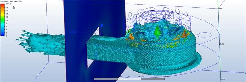
Circulation Pump Simulated Using Computational Fluid Dynamics Software
When so much is at stake, why take the chance on a sub-par system?
Downtime is a direct hit to the bottom line.
Talk to one of our engineers today to discuss a full comprehensive solution!